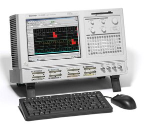
For several of our projects we have had to use a Logic Analyser to determine the proper working of an existing system. The results of a captured session on the Logic Analyser is a large binary file representing the state of all 136 of its inputs, over a period of time, at around 2ns granularity. This gives an enormous amount of data which must be then viewed by the operator to determine where a problem lies. Some aspects of this can be eased through the user interface on the Logic Analyser - colouring relevant lines, or giving textual labels to certain values. But mostly it is a manual process. We have developed a protocol definition system which allows us to describe the protocol, and then automatically process the traces from the Logic Analyser, decoding the results into a human readable form. This give a double benefit - we can analyse an existing system to determine how it is working, producing our parser as we go, and once this is completed we can then run it against our own implementation to verify that it conforms to the original system. As the Logic Analyser is a completely generic digital interface, it can process almost any signaling system. Using this technique we have written protocol definitions for the following buses:
- 8250-compliant UART bus
- Kennedy tape drive bus
- Pertec tape drive bus
- SCSI bus
- NAND control & data bus
- PCI bus
- SPI bus
- CFI-compliant NOR flash bus
- DM9000 Ethernet controller bus
- Image Sensor interface bus


