
Form Factor
Introduction
The form factor of an embedded device refers to its size, shape and weight. Some embedded devices have very strict form factor requirements. For example a cellphone needs to be light, designed to be easy to hold and use as a phone, and small enough to fit in a pocket. Other embedded devices, such as data storage units, have much less strict form factor requirements.
A number of things can help reduce the size of an embedded device when targeting a small form factor:
- Removing any unnecessary components from the design. For example, choosing one of Wi-Fi or GPRS for Internet connectivity rather than using both.
- Choice of components. Similarly functioning components from different manufactures can have very different form factors. Many components are also available in two or more form factors.
- Some functions which are typically performed using hardware may be able to be replaced with either a software or an FPGA solution to reduce board space.
- Attention to layout. By spending extra time on the layout of a board it is possible to reduce the final size by up to 40% in some cases.
Development Boards
While the finished product for an embedded device may have a small form factor it is not ideal to work with small form factor boards during development. Bluewater Systems has a large amount of experience in developing large size development boards which are schematically identical to the small form factor boards used for the final product. The larger development boards simplify probing and modding the board, and allow for additional test access, such as mictor connectors for logic analysers, to be added. Though development boards may appear to unnecessary or costly, they can greatly reduce development time and help produce a better final product.
In addition to the large size development boards, Bluewater Systems has also developed a test access board called Squid which provides serial, JTAG and Ethernet debugging which is connected to a board using a small 11mm by 9mm connector. Squid is useful for providing debugging access on small form factor boards, but does not replace the need for the large size development boards.
For designs where the hardware is either very simple or the design has been previously proven, the development board stage can be skipped. In the case of the Rig 200, Bluewater Systems did not produce a development board since much of the design had been proven through the Rig 100 and various other earlier projects. Bluewater Systems discusses the need for development boards with customers on a case by case basis.
Bluewater Systems Experience
Bluewater Systems has developed a number of small form factor boards for a wide range of applications. Our skilled engineers have proven expertise in developing small embedded devices.
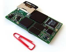
Snapper System Modules

The Snapper range of system modules have been designed for a small, uniform form factor. Our Snapper System modules pack an ARM CPU, Ethernet, USB, LCD controller and many other features onto a board with a smaller footprint than a standard business card. The Snapper CL15, for example, measures only 40mm by 70mm, has a thickness of 12mm and weighs just 17 grams. This small size enables the Snapper system modules to be used in conjunction with a custom small form factor carrier board. For embedded devices with very strict form factor requirements, all, or part of a Snapper system can be directly embedded on the baseboard. This saves space by removing the need for the Snapper connectors and any unnecessary components.
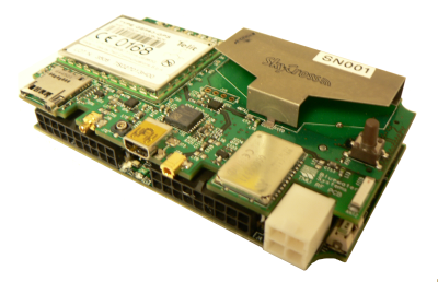
Dory


Bluewater Systems developed a complex vehicle tracking system, project name 'Dory', which integrates a Snapper CL15, GPS, GPRS, Bluetooth, 1GB of storage and a wide range of IO options. The design had very strict form factor requirements. The first step Bluewater Systems made in minimising the size of the unit was to embedded the design of the Snapper CL15 directly on to the baseboard. Secondly the design was split into two separate boards, one with the Snapper CL15 and most of the IO components and the other with most of the connectivity components (GPRS, GPS, Bluetooth, etc). The two boards are stacked, one on top of the other, and connected using a pair of pin connectors. The final dimensions of the unit are 90mm by 50mm, with a height of 25mm. Included on the final board is a Squid connector to allow for easy production testing of the units.
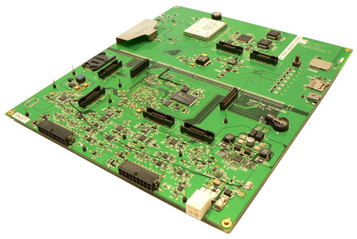
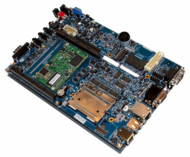
A large size development, shown below, board was also produce for Dory. Although the development is a single PCB, it is split into two separate parts by a series of 0 Ohm resistors. The pin connectors for joining the two smaller boards are also present, with the same physical layout on the development board. This allows either the development board to be split in two and stacked, or for one half of the small form factor board to be tested with the development board. The development board also contains seven mictor probes for logic analyser access and a number of easy access ground pins to aid probing. A number of manual mods are visible on the development board, which would be much more difficult to do on a small form factor production board.
DDS XM-100 Series

The DDS XM-100 is data storage unit used to replace old magnetic tape drives typically found in telephone exchanges. The form factor for the DDS-XM100 has been designed to be discrete, yet large enough to provide easy access to the controls on the front of the unit and the connectors on the rear. The original design is a horizontal casing, however this form factor does not suit all installation sites. A second form factor, called the DDS-XM100S, was designed to suit these installation sites. Internally the DDS-XM100 and DDS-XM100S are identical, however the controls on the outside of the DDS-XM100S have been rotated and the software modified to display on a vertically orientated screen rather than a horizontal one.
Form factor of the Rig 200

The Rig 200 has also been designed for a convenient small form factor. The Rig 200 was designed around the shape of a standard 5.25 inch CD-ROM bay. It measures only 199mm by 140mm, while retaining enough space to provide nine mounting holes for fixing the board securely. The option modules for the Rig 200 also have a standard form factor of roughly half the size of the Rig 200 baseboard (100mm by 140mm). The connectors for the Rig 200 option modules are available in a number of heights to suit the needs of the module. The standard Rig 200 connectors are 11mm high.


